
- #Dfrobot lcd keypad layout how to#
- #Dfrobot lcd keypad layout serial#
- #Dfrobot lcd keypad layout code#
- #Dfrobot lcd keypad layout windows#
Serial display - Accepts serial input, displays it. TextDirection - Control which way text flows from the cursor.
#Dfrobot lcd keypad layout how to#
Hello World! - How to wire an LCD display and bring it to life.īlink - Control of the block-style cursor.Ĭursor - Control of the underscore-style cursor.ĭisplay - Quickly blank the display without losing what's on it. Liquid Crystal Library - Your reference for the Liquid Crystal library.

But you can change the size of // your LCD using them:Ĭonst int numCols = 16 void setup ( ) See Also */ // include the library code: # include // initialize the library by associating any needed LCD interface pin // with the arduino pin number it is connected toĬonst int rs = 12, en = 11, d4 = 5, d5 = 4, d6 = 3, d7 = 2 LiquidCrystal lcd (rs, en, d4, d5, d6, d7 ) // these constants won't change.
#Dfrobot lcd keypad layout code#
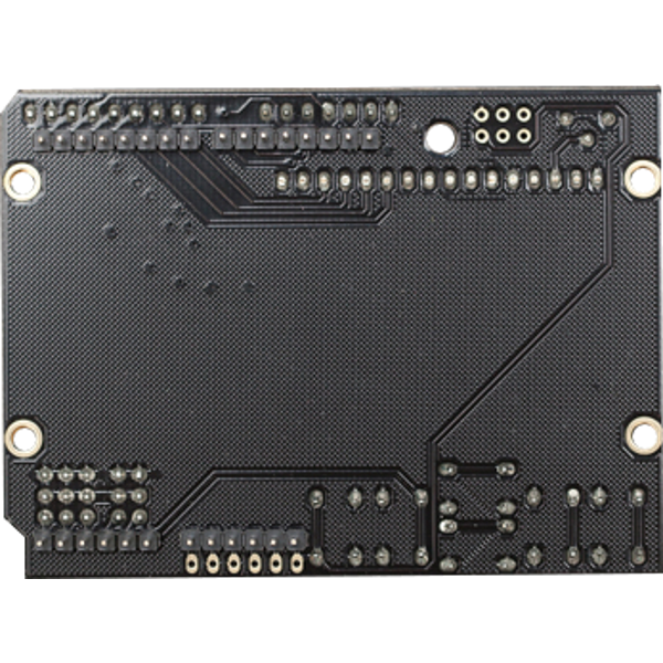
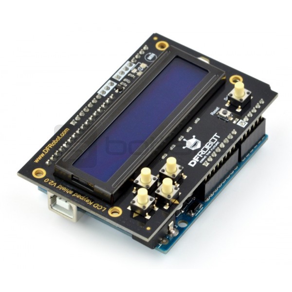
This example code is in the public domain. This sketch prints to all the positions of the LCD using the There are many of them out there, and youĬan usually tell them by the 16-pin interface. Library works with all LCD displays that are compatible with the The keypad consists of 5 keys select, up, right, down and left. It consists of a 1602 white character blue backlight LCD. For more circuit examples, see the Fritzing project page Codeĭemonstrates the use a 16x2 LCD display. The LCD Keypad shieldis developed for Arduino compatible boards, to provide a user- friendly interface that allows users to go through the menu, make selections etc. For more circuit examples, see the Fritzing project page Schematic A 220 ohm resistor is used to power the backlight of the display, usually on pin 15 and 16 of the LCD connector Just one thing to mention, they all happen to have a flaw in the design, so dont use pin 10 when using this shield. To wire your LCD screen to your board, connect the following pins:Īdditionally, wire a 10k pot to +5V and GND, with it's wiper (output) to LCD screens VO pin (pin3). Pin headers to solder to the LCD display pinsīefore wiring the LCD screen to your Arduino board we suggest to solder a pin header strip to the 14 (or 16) pin count connector of the LCD screen, as you can see in the image above. LCD Screen (compatible with Hitachi HD44780 driver) setCursor ( 15, 1 ) // bottom right Hardware Required To set the backlight off, set pin 10 as output, and immediately set output low (never high!)įor more information, there is discussion on the Arduino forums about this.Lcd.To set the backlight on, set pin 10 as input.This may cause the over stressing of the MCU and may reduce its life, or maybe even blow it up. But in the design, a flaw exists, that when pin 10 is set to output, and set high, it could cause the IO pin of the MCU (the main Atmel chip) to deliver too much current (over the datasheet’s maximum rating) to the backlight LED. The library has functions to enable and disable the backlight. Expanded Analog Pinout with standard DFRobot configuration for fast sensor. Just one thing to mention, they all happen to have a flaw in the design, so don’t use pin 10 when using this shield. This is a very popular LCD Keypad shield for Arduino or Freeduino board. Update: This existed in 2013, but haven't checked this in 2021.

This has been tested on Arduino 1.8.16 IDE. This is a very popular LCD Keypad shield for Arduino or Freeduino board. Start Arduino and you should be able to open the example from the menu.
#Dfrobot lcd keypad layout windows#
This libraries directory on Windows by default is c:\Users\USERNAME\Documents\Arduino\libraries\. To install, it simply copy the DFR_LCD_Keypad directory into the libraries/ directory. LCD and Keypad Library for DFRobot LCD Keypad Arduino Shield


 0 kommentar(er)
