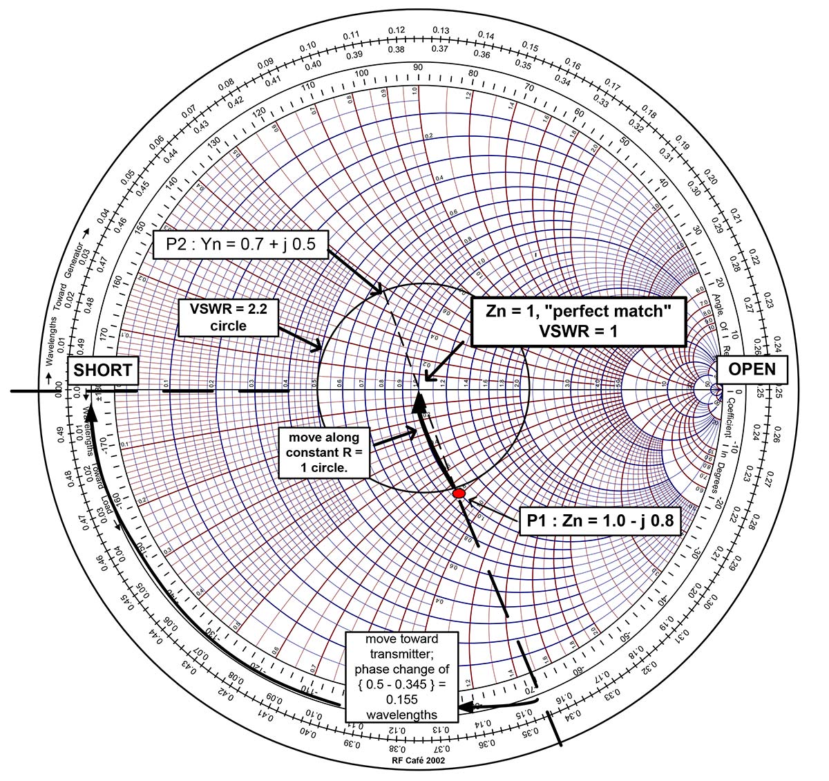

The complete circles on the chart are the constant resistance circles. The line goes from zero resistance on the left side to infinite resistance on the right side.

The straight horizontal line through the center of the chart is the 0 reactance line. 1) has groupings of circles and portions of circles. The Smith chart is a graphical representation of impedance, admittance (the reciprocal of impedance), phase, wavelength and the reflection coefficient. One of the better tools available to the broadcast engineer for troubleshooting SWR issues is the Smith chart invented by Phillip Hagar Smith in the 1930s. Bird Electronics and Coaxial Dynamics build power meters that measure the traveling wave. If the meter is measuring the traveling waves, the location of the meter or the length the transmission line will not affect the meter reading. If the length of the transmission line is changed, the voltage at the sample point will change. If the meter is measuring the standing wave voltage, that voltage will vary depending upon the sample point location along the transmission line. The frequency of the wave and the length of the transmission line are fixed and unchanging, therefore the locations of the standing waves within the transmission line are fixed and unchanging as well.ĭepending upon the type of the power metering in a transmitter system, the meter may be measuring the standing wave voltage at the test point, or it may be measuring the traveling waves. Depending upon the phase of the incident wave and the reflected wave, the interference may be constructive or destructive. These two traveling waves will interact with each other along the transmission line, in an interference pattern that creates standing waves. If the line is not terminated in the characteristic impedance of the line by a load (antenna), there will be a reflection that travels back toward the transmitter. (Read it at /swr.) The forward power travels towards the (antenna) load end of the transmission line. 9, 2015 issue, I described SWR as the standing wave ratio of forward and reflected power. In my previous article “The ABCs of SWR, VSWR, Reflected Power and Return Loss” in the Dec. Let’s consider what happens when the transmission line length is changed. You have probably heard the statement about standing wave ratio: “I changed the length of the transmission line and reduced the SWR.” Or the opposite statement, “I changed the length of the transmission line and the SWR increased.” Another statement we hear is, “I put a ‘trombone section’ in the transmission line and adjusted the length until the transmitter operated properly.”


 0 kommentar(er)
